I couldn't find a solid write-up for how the Spektrum DX6i Trainer protocol actually works, so here's my attempt.
With 2 DX6i's (the officially recommended way), the trainer mode is pretty simple. The Master transmitter powers on and connects to the model, you plug a magic trainer cable (3.5mm mono audio cable) into the Master then into the Student and that's about it. The Student transmitter will power on on its own and the Master can hand-off to the Student by just flipping the switch. There's no settings or anything to configure, and not a whole lot of instructions.
I did not have a magic trainer cable (who's used mono audio in the past 20 years?) or another radio, so I tried something different. I opened up the radio (a whole 6 screws), and found the trainer daughter-board in the back.
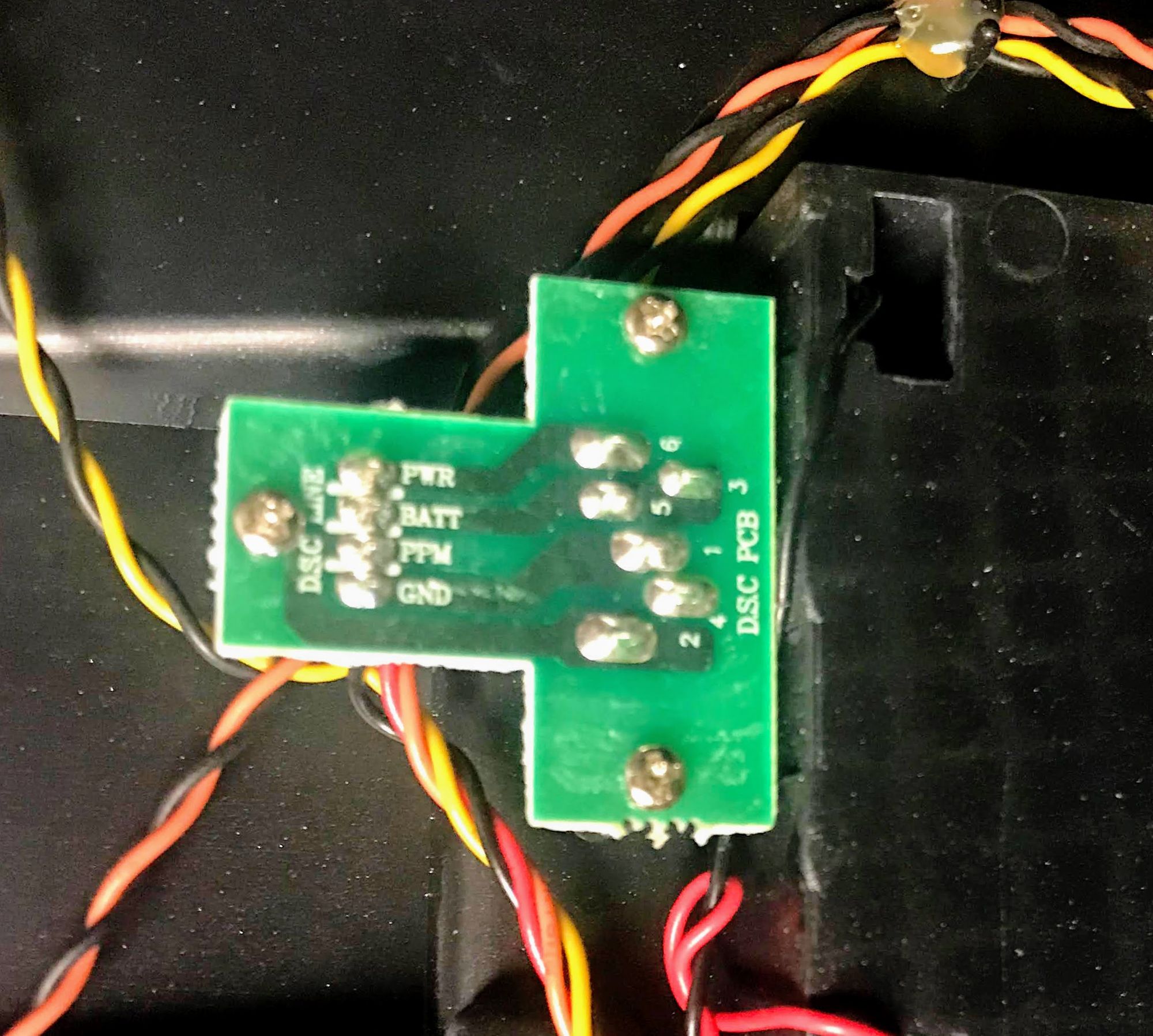
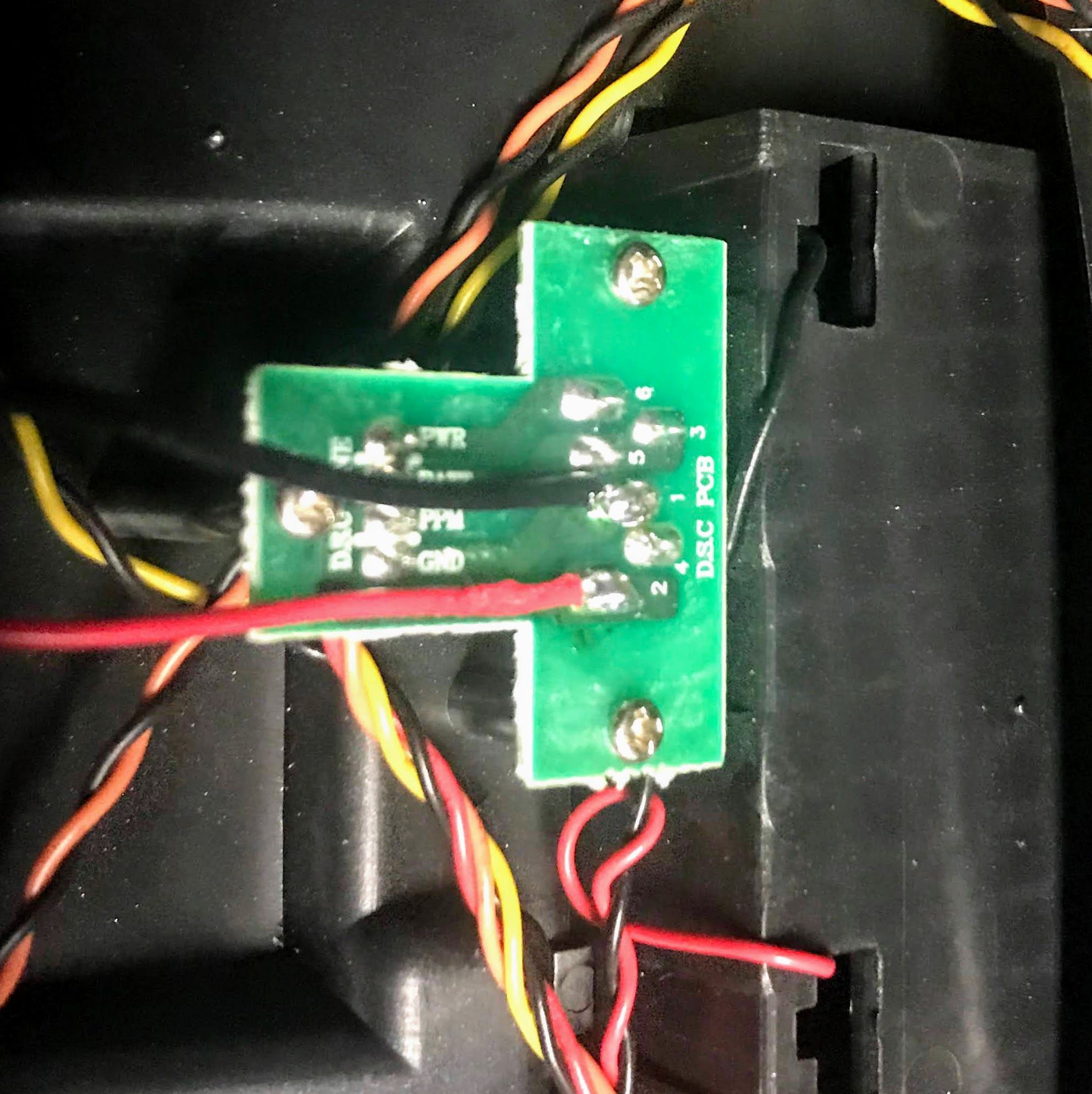
Interestingly enough, the 2 wire training cable has 6 pins and 4 different wires. I soldered fly leads onto the PPM and GND lines to see if there was any usable signal. Spoiler alert: there was none. From the convenient silkscreen labels, it looks like plugging in the cable connects PWR & BATT to power on the radio. This also seems to let the transmitter know that it is the "Student" and should send PPM.
To verify my hypothesis I bodged together a "Trainer Cable" using a standard Aux cable and some breadboard jumpers. The PPM line is broken out to the Tip of the cable, and the Ring and Socket are bridged for the GND line.
Once I was seeing any signal on the line, I connected the jumpers to my knockoff logic analyzer.
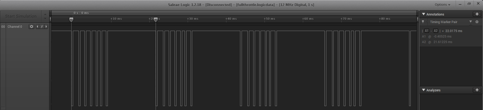
From the logic analyzer, its clear the Trainer Student Data is PPM with a 22ms frame and 6 channels of data. Working out the channel mapping with just the logic analyzer is doable, but tedious. Luckily in the age of Arduino, there's a library for that.
I connected my "Trainer Cable" to an Arduino Uno and grabbed the PPM-reader library from Nikkilae/PPM-reader.
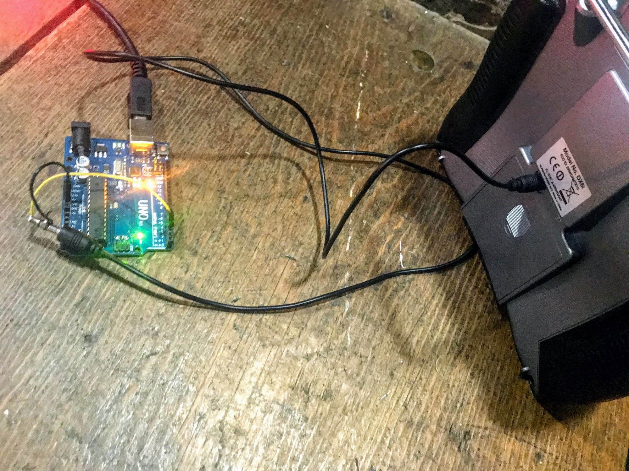
The example code is more than enough to determine the channel mapping, and get some fun graphs. It also made it obvious that I forgot to turn off my mixes. My reader/plotter code is on my Gitlab here.
From this the channel mapping appears to be Throttle, Aileron, Elevator, Rudder, Ch5 (Gear/Mode Sw), Aux. My Tx seems to have a range of about 1100-1920us.
The obvious follow up question is: can we write to it?
Using PPMEncoder from schinken/PPMEncoder I threw together some test code that would set all channels to the mid-point and sweep the Elevator Channel (available on Gitlab).
It works! Before the video started, the radio and model were powered on and allowed to bind, then my "Trainer Cable" was connected. Control is handed off to my Arduino by holding the Trainer switch (which is sadly spring loaded).
Its also worth mentioning that the Master appears to transmit the Student PPM Data directly (the model on the radio has mixes for steering and a bit of correction that were not applied to the Student data).
